mirror of
https://github.com/nopnop2002/esp-idf-ssd1306.git
synced 2024-09-19 17:56:25 -04:00
163 lines
6.4 KiB
Markdown
163 lines
6.4 KiB
Markdown
# esp-idf-ssd1306
|
|
SSD1306/SH1106 driver for esp-idf
|
|
|
|
I used [this](https://github.com/yanbe/ssd1306-esp-idf-i2c) repository as a reference.
|
|
I used [this](https://github.com/dhepper/font8x8) font file.
|
|
|
|
# Software requirements
|
|
ESP-IDF V4.4/V5.x.
|
|
|
|
__Note for ESP32C2.__
|
|
ESP-IDF V5.0 ESP32C2 i2c driver has a bug.
|
|
ESP-IDF V5.1 is required when using i2c of ESP32C2.
|
|
|
|
__Note for ESP32C6 and ESP32H2.__
|
|
ESP-IDF V5.1 is required when using ESP32C6 and ESP32H2.
|
|
|
|
__Note for ESP-IDF V5.2.__
|
|
A new i2c driver is now available in ESP-IDF V5.2.
|
|
Under ESP-IDF V5.2 this project uses a new i2c driver.
|
|
|
|
# Installation
|
|
|
|
```
|
|
git clone https://github.com/nopnop2002/esp-idf-ssd1306
|
|
cd esp-idf-ssd1306/TextDemo/
|
|
idf.py set-target {esp32/esp32s2/esp32s3/esp32c2/esp32c3/esp32c6/esp32h2}
|
|
idf.py menuconfig
|
|
idf.py flash
|
|
```
|
|
|
|
__Note for ESP32C3__
|
|
For some reason, there are development boards that cannot use GPIO06, GPIO08, GPIO09, GPIO19 for SPI clock pins.
|
|
According to the ESP32C3 specifications, these pins can also be used as SPI clocks.
|
|
I used a raw ESP-C3-13 to verify that these pins could be used as SPI clocks.
|
|
|
|
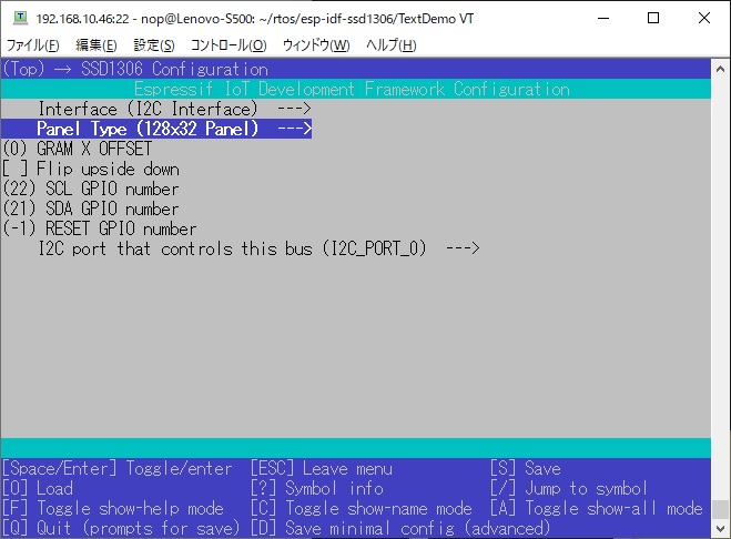
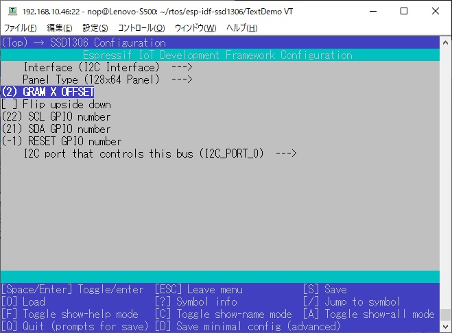
# Configuration
|
|
You have to set this config value with menuconfig.
|
|
- CONFIG_INTERFACE
|
|
- CONFIG_PANEL
|
|
- CONFIG_OFFSETX
|
|
- CONFIG_FLIP
|
|
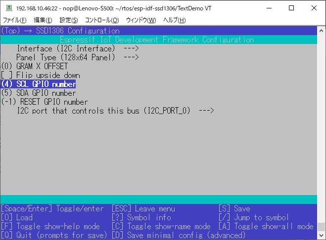
- CONFIG_SDA_GPIO
|
|
- CONFIG_SCL_GPIO
|
|
- CONFIG_RESET_GPIO
|
|
- CONFIG_MOSI_GPIO
|
|
- CONFIG_SCLK_GPIO
|
|
- CONFIG_CS_GPIO
|
|
- CONFIG_DC_GPIO
|
|
|
|
|
|

|
|
|
|
---
|
|
|
|
# Generic SSD1306 128x32 i2c
|
|
|
|

|
|
|
|
|
|
# Generic SSD1306 128x64 i2c
|
|
|
|

|
|

|
|
|
|
# Generic SH1106 128x64 i2c
|
|
__Hardware scroll Not support__
|
|
Left:1.3 inch SH1106
|
|
Right:0.96 inch SSD1306
|
|
|
|

|
|
|
|
|
|
# 128x64 TTGO
|
|
Unlike other ESP32 development boards, the RTC_CLOCK crystal on this board uses a 26MHz one.
|
|
You need to change the RTC CLOCK frequency to 26MHz using menuconfig.
|
|
|
|

|
|

|
|

|
|

|
|
|
|
# 128x64 ESP-WROOM-32
|
|
|
|

|
|
|
|
|
|
---
|
|
|
|
# Generic SSD1306 128x32 SPI
|
|
|
|

|
|

|
|
|
|
|
|
# Generic SSD1306 128x64 SPI
|
|
D0 is SCLK.
|
|
D1 is MOSI.
|
|
|
|

|
|

|
|
|
|
|
|
# Generic SH1106 128x64 SPI
|
|
__Hardware scroll Not support__
|
|
Left:1.3 inch SH1106
|
|
Right:0.96 inch SSD1306
|
|
|
|

|
|

|
|
|
|
---
|
|
|
|
# I2C Clock speed
|
|
According to the SSD1306 datasheet, the minimum i2c clock cycle time is 2.5us.
|
|
Therefore, the maximum i2c clock frequency is 400KHz.
|
|
The i2c clock frequency used by this project is 400KHz.
|
|
|
|
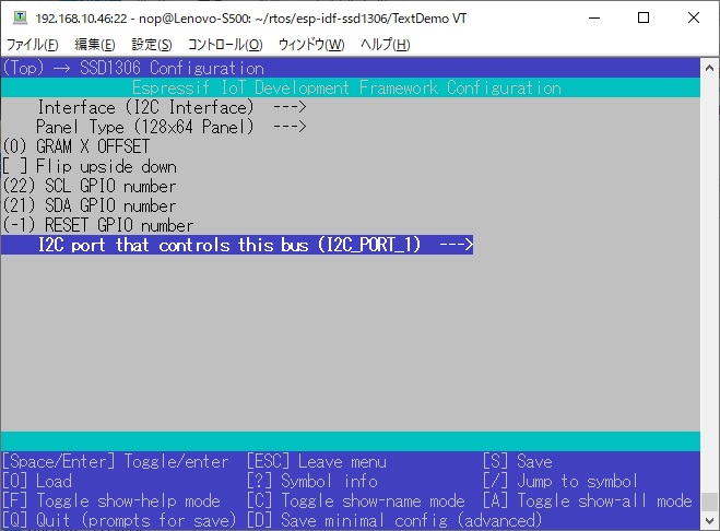
# I2C Port selection
|
|
|
|
|
|
The ESP32 XTENSA series has two I2C Ports.
|
|
You can use these two ports freely.
|
|
If you use this module at the same time as another I2C device using I2C port 0, you must change it to I2C port 1.
|
|
|
|
---
|
|
|
|
# SPI Clock speed
|
|
According to the SSD1306 datasheet, the minimum SPI clock cycle time is 100ns.
|
|
Therefore, the maximum SPI clock frequency is 10MHz.
|
|
The SPI clock frequency used by this project is 1MHz.
|
|
Higher SPI clock frequencies can be specified using ```spi_clock_speed()```.
|
|
When using 10MHz, you need to be careful about the length of the wire cable.
|
|
```
|
|
//int speed = 1000000; // 1MHz
|
|
//int speed = 2000000; // 2MHz
|
|
//int speed = 4000000; // 4MHz
|
|
//int speed = 6000000; // 6MHz
|
|
//int speed = 8000000; // 8MHz
|
|
int speed = 10000000; // 10MHz
|
|
spi_clock_speed(speed);
|
|
spi_master_init(&dev, CONFIG_MOSI_GPIO, CONFIG_SCLK_GPIO, CONFIG_CS_GPIO, CONFIG_DC_GPIO, CONFIG_RESET_GPIO);
|
|
```
|
|
|
|
# SPI BUS selection
|
|

|
|
|
|
The ESP32 XTENSA series has three SPI BUSs.
|
|
SPI1_HOST is used for communication with Flash memory.
|
|
You can use SPI2_HOST and SPI3_HOST freely.
|
|
When you use SDSPI(SD Card via SPI), SDSPI uses SPI2_HOST BUS.
|
|
When using this module at the same time as SDSPI or other SPI device using SPI2_HOST, it needs to be changed to SPI3_HOST.
|
|
When you don't use SDSPI, both SPI2_HOST and SPI3_HOST will work.
|
|
Previously it was called HSPI_HOST / VSPI_HOST, but now it is called SPI2_HOST / SPI3_HOST.
|
|
|
|
---
|
|
|
|
# Flip upside down
|
|
|
|

|
|
|
|

|
|
|