---
layout: tutorial
---
# ESP RAINMAKER TUTORIAL
This tutorial walks you through the most important steps required for provisioning device powered by ESP32-WROOM, ESP32-S2 or ESP32-C3 module.
__Minimum Requirements:__
ESP32-WROOM, either a Module or DevKit
Wi-Fi Access Point, preferrably with dedicated vLAN for IoT devices
Smart phone with RainMaker installed
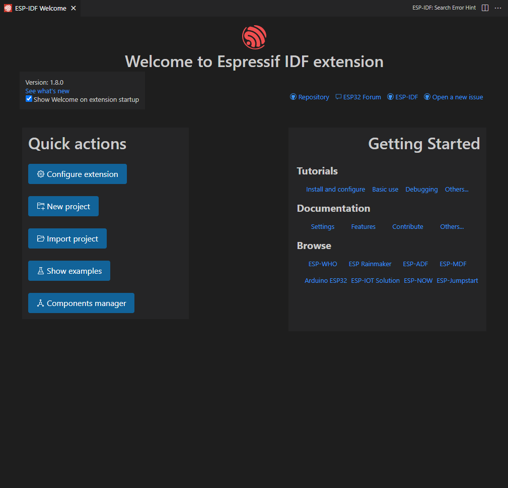
### I. ESP-IDF: Create a New Project
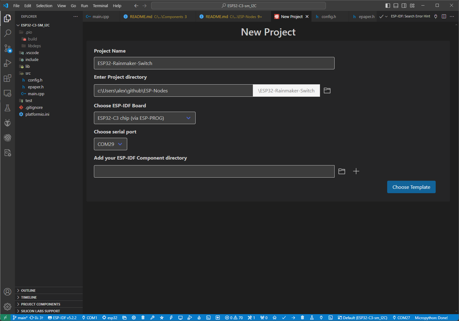
The first step is to create a new project with ESP-IDF Rainmaker extention using Visual Studio Code.
 Specify the project name, directory path and ESP32 module that will be used (i.e. ESP32-WROOM, ESP32-S2 or ESP32-C3). In addition, you may specify the Serial port where ESP32 Module is connected to; the serial port can be changed latter, if neccessary.
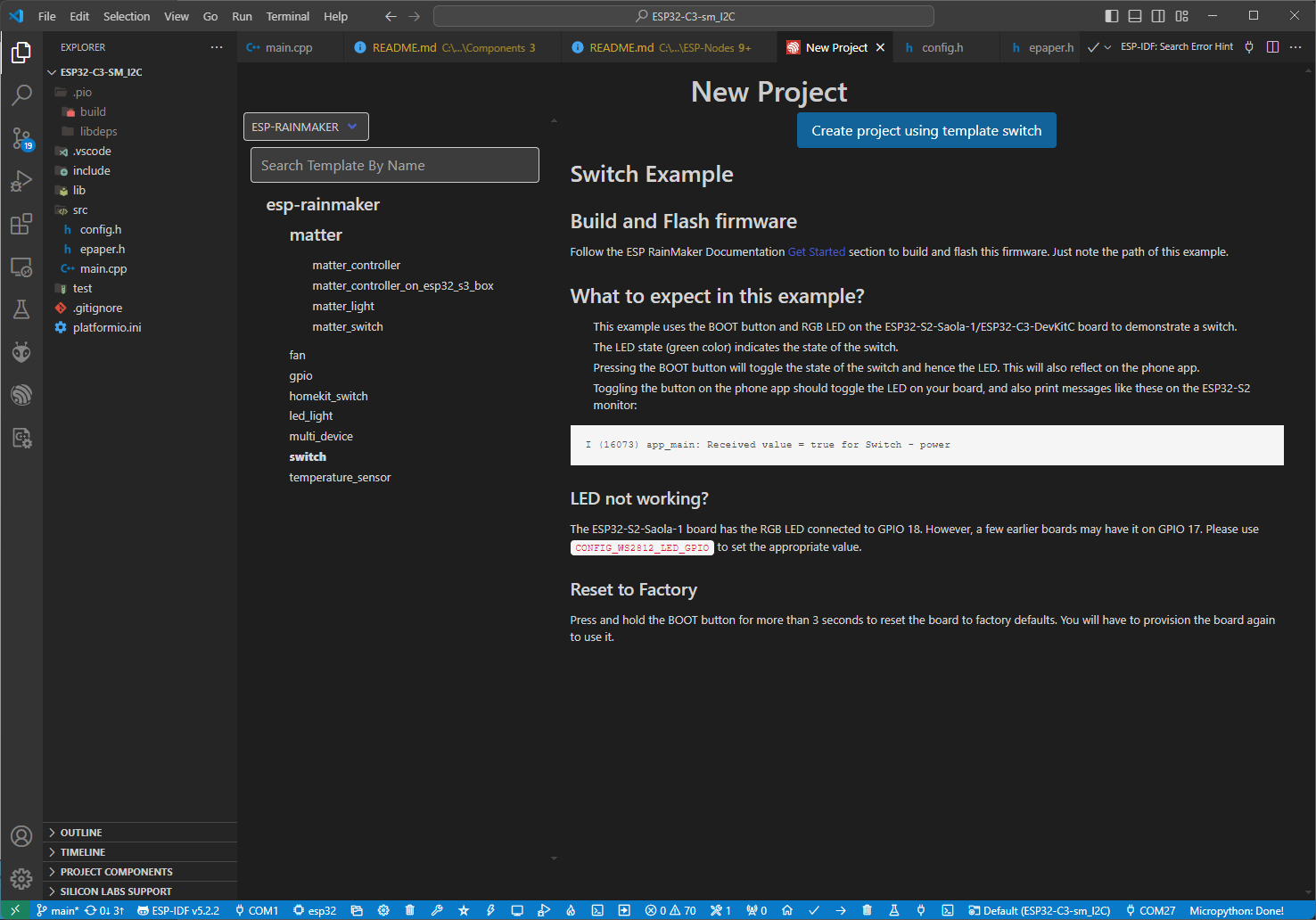
 On the next screen, select the ESP Rainmaker extention and choose the example code to start with. For this tutorial, an example code for __Switch__ was selected. Click "Create project using template switch".
 ### II. Modify the Template Code
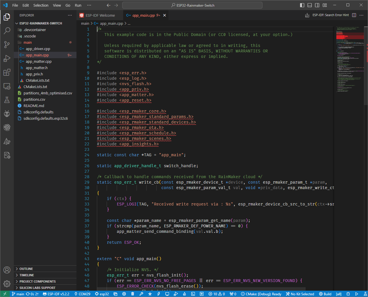
Once project is created, make the following changes to the **app_main.cpp** source file.
Change the TAG variable to reflect your device name as follows:
```C++
static const char *TAG = "ESP32-Nodes app main";
```
```C++
esp_rmaker_node_t *node = esp_rmaker_node_init(&rainmaker_cfg, "ESP RainMaker Device", "Switch");
```
```C++
switch_device = esp_rmaker_device_create("ESP32-Nodes Switch", ESP_RMAKER_DEVICE_SWITCH, NULL);
```
### II. Modify the Template Code
Once project is created, make the following changes to the **app_main.cpp** source file.
Change the TAG variable to reflect your device name as follows:
```C++
static const char *TAG = "ESP32-Nodes app main";
```
```C++
esp_rmaker_node_t *node = esp_rmaker_node_init(&rainmaker_cfg, "ESP RainMaker Device", "Switch");
```
```C++
switch_device = esp_rmaker_device_create("ESP32-Nodes Switch", ESP_RMAKER_DEVICE_SWITCH, NULL);
```
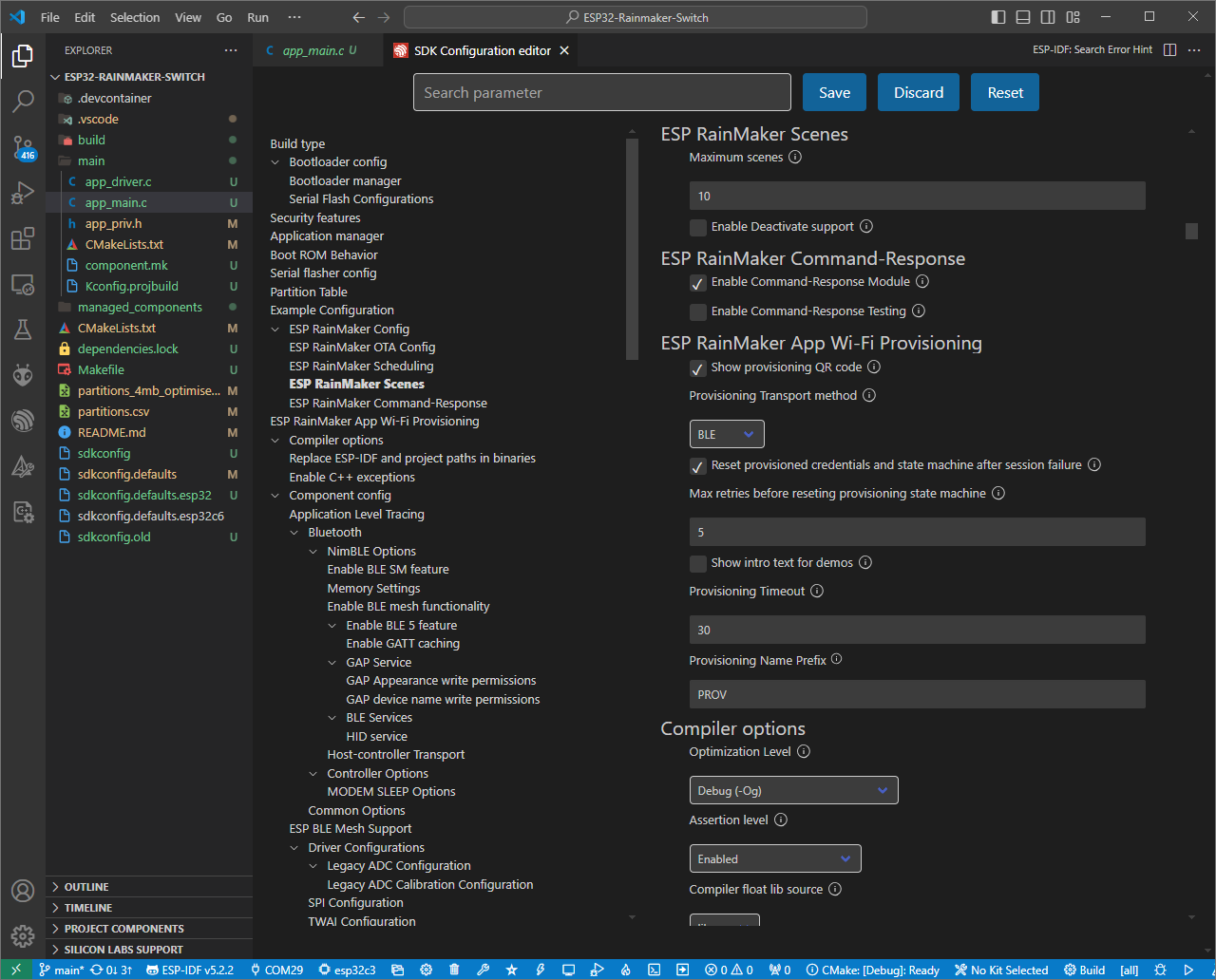
 ### III. Modify Configuration
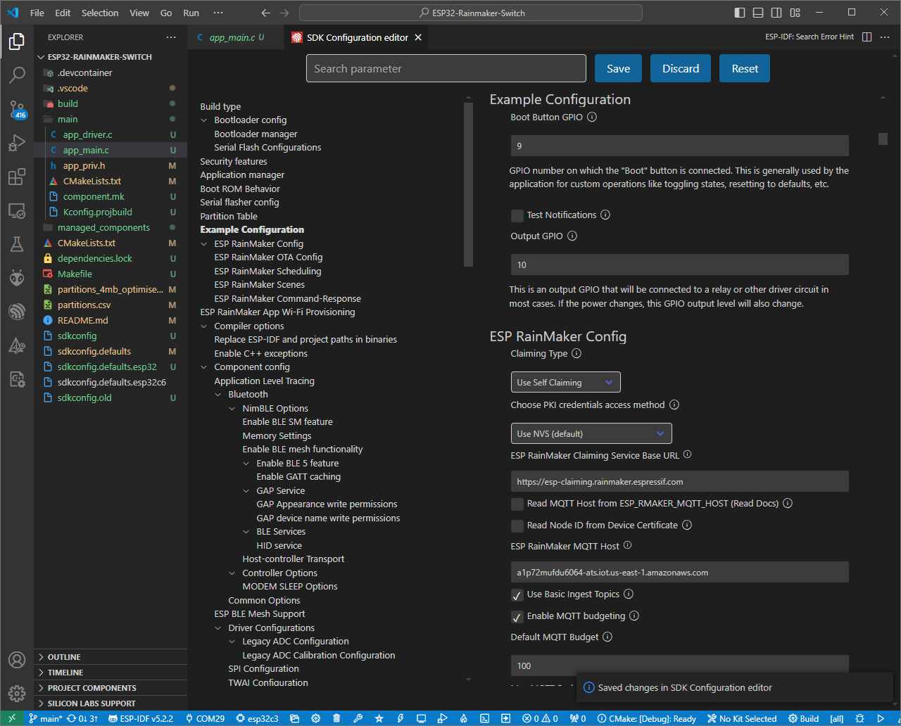
ESP-IDF **menuconfig** contains settings that define hardware configuration. For example, GPIO used to control power relay, etc. To set configuration values, navigate to the ESP-IDF: SDK Configuration Editor (menuconfig). Some of the default values are pre-defined by the RainMaker Switch template; however, the specific number of GPIO used to turn LED Lights on or off needs to be entered.
To do so, click on Example Configuration section, and change **Output GPIO** value to _4_, which corresponds to the GPIO connected to the LED lights control pin.
Set **Claiming Type** to _Assisted_, and **Provisioning Transport Method** to _BLE_.
### III. Modify Configuration
ESP-IDF **menuconfig** contains settings that define hardware configuration. For example, GPIO used to control power relay, etc. To set configuration values, navigate to the ESP-IDF: SDK Configuration Editor (menuconfig). Some of the default values are pre-defined by the RainMaker Switch template; however, the specific number of GPIO used to turn LED Lights on or off needs to be entered.
To do so, click on Example Configuration section, and change **Output GPIO** value to _4_, which corresponds to the GPIO connected to the LED lights control pin.
Set **Claiming Type** to _Assisted_, and **Provisioning Transport Method** to _BLE_.
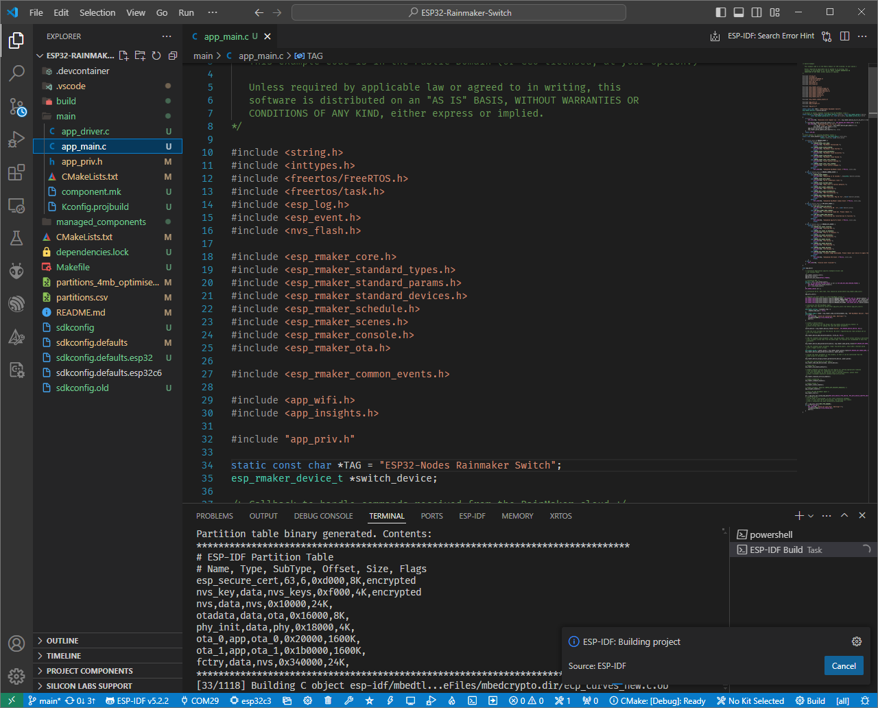
 Click _Save_ and then build the project by running the command _ESP-IDF: Build Project_.
 Building the project can take some time.
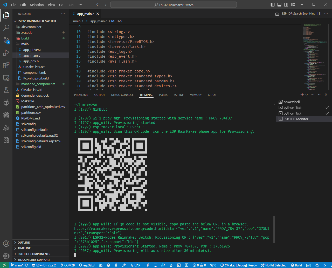
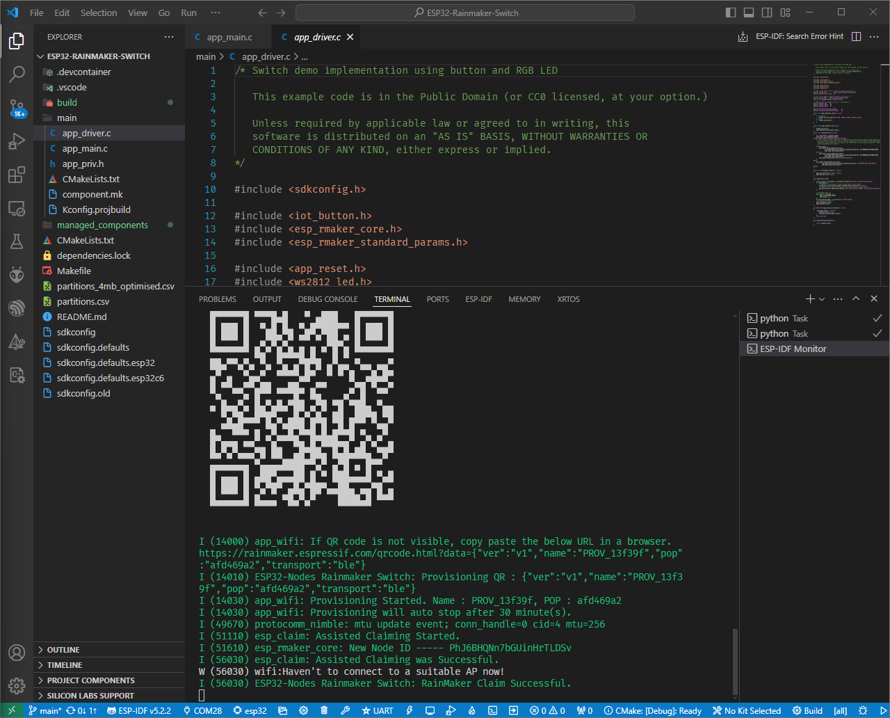
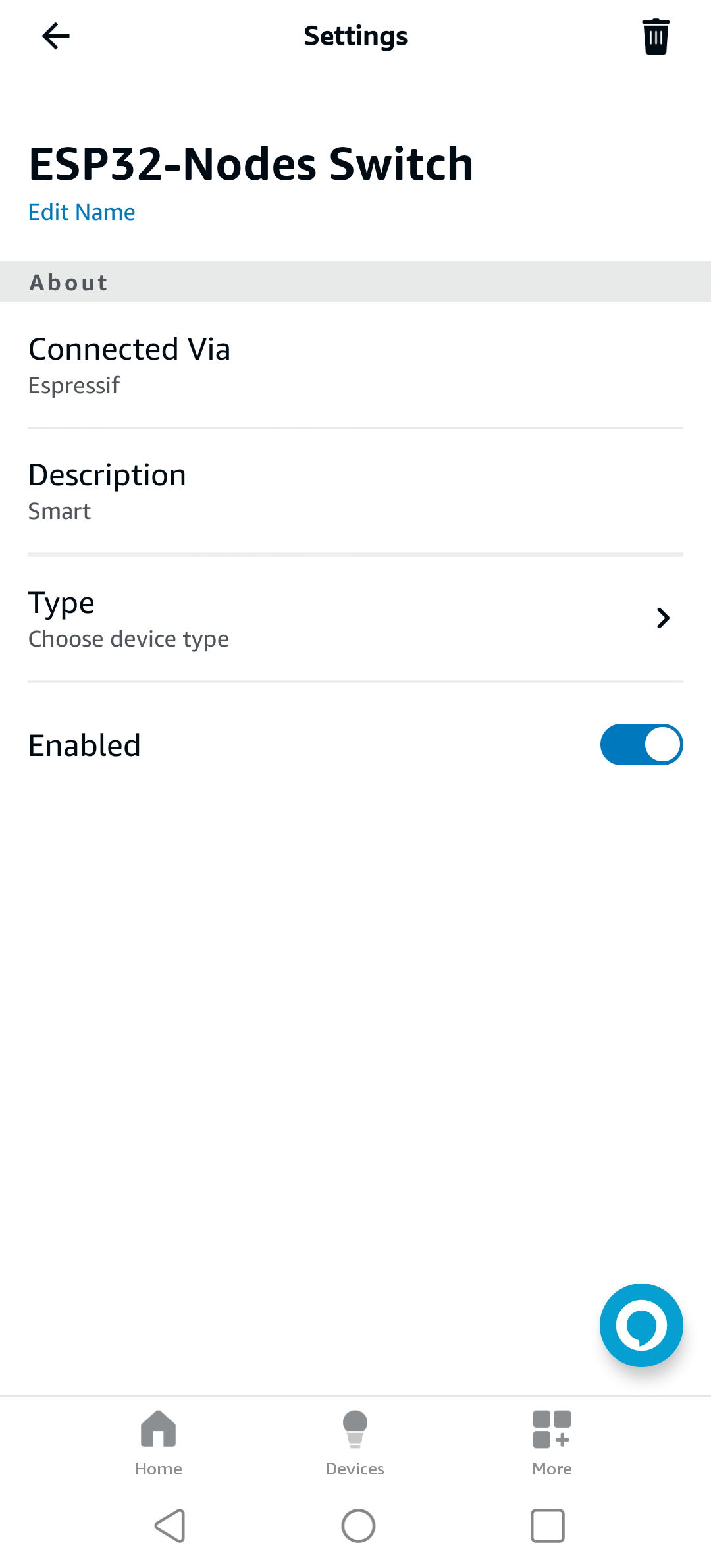
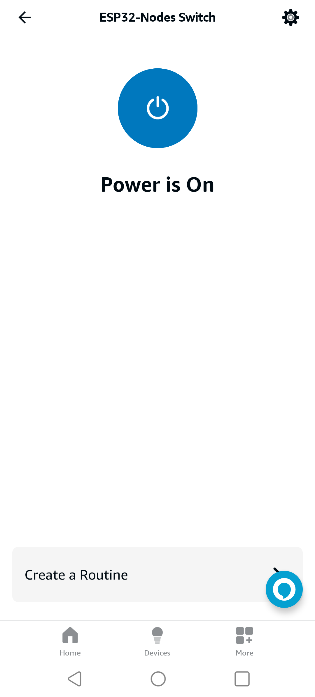
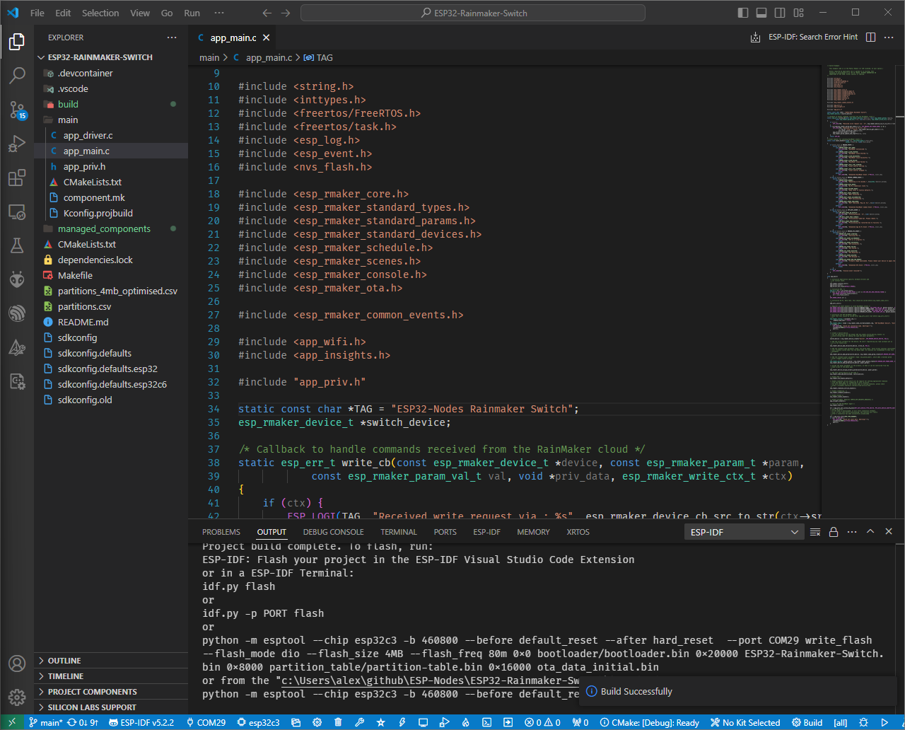 ### Adding RainMaker Device
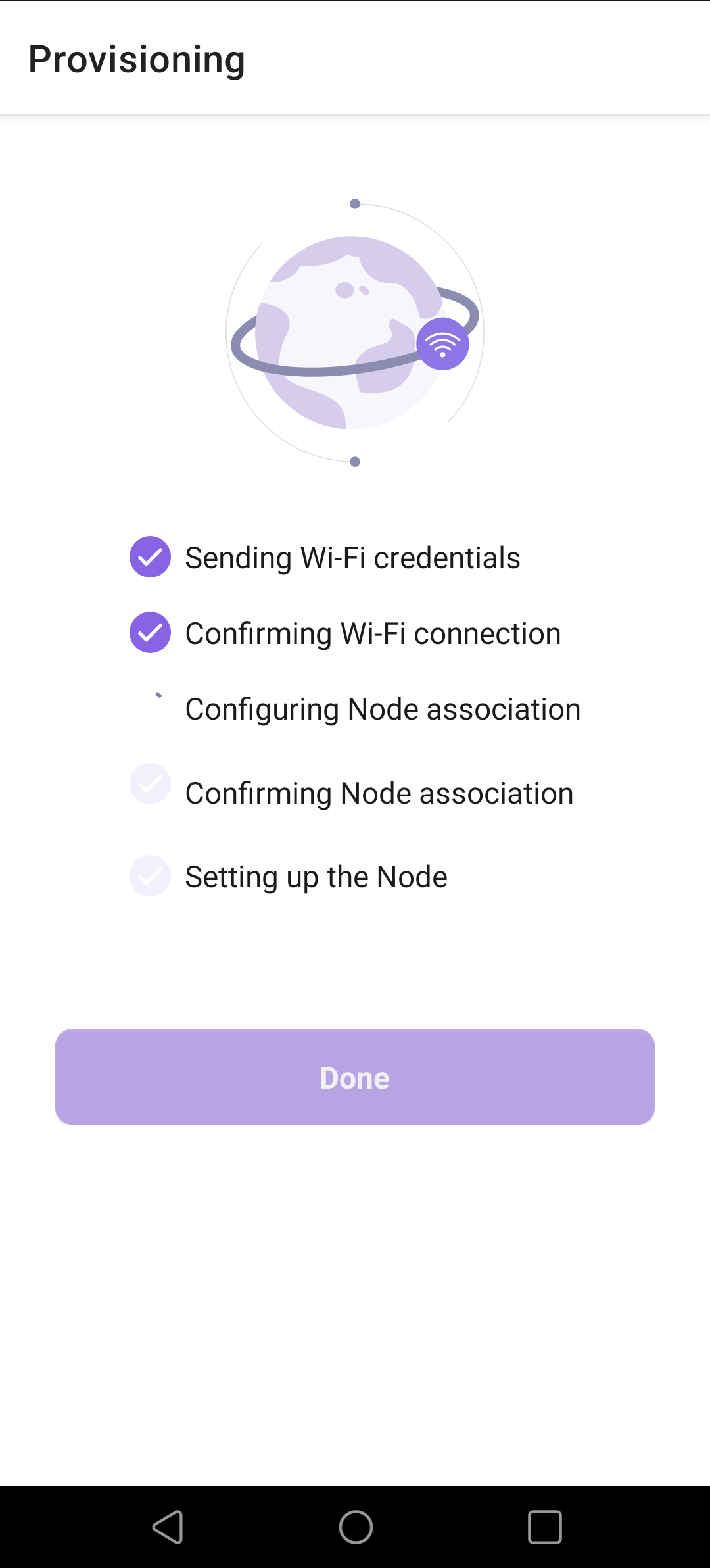
Once project is successfully built, and ESP32-WROOM module is flashed, reboot your device and open Serial Monitor in order to access provisioning QR code. At this point you can start adding your device to your RainMaker dashboard. On your smartphone, launch the _ESP RainMaker_ app and click _Add device_. You'll be asked to scan the QR code. If provisioning is successful, _ESP RainMaker_ app will take you to the nest steps.
### Adding RainMaker Device
Once project is successfully built, and ESP32-WROOM module is flashed, reboot your device and open Serial Monitor in order to access provisioning QR code. At this point you can start adding your device to your RainMaker dashboard. On your smartphone, launch the _ESP RainMaker_ app and click _Add device_. You'll be asked to scan the QR code. If provisioning is successful, _ESP RainMaker_ app will take you to the nest steps.